


MTW European Type Trapezium Mill
Input size:30-50mm
Capacity: 3-50t/h
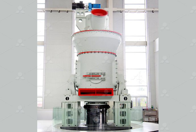
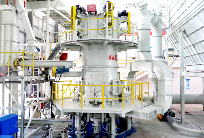
LM Vertical Roller Mill
Input size:38-65mm
Capacity: 13-70t/h
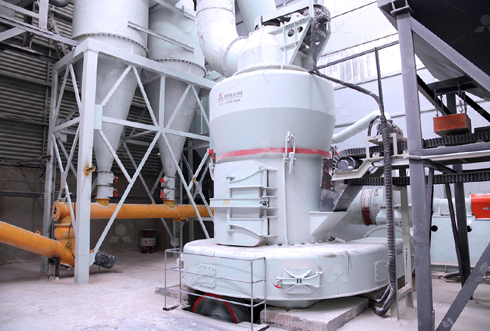
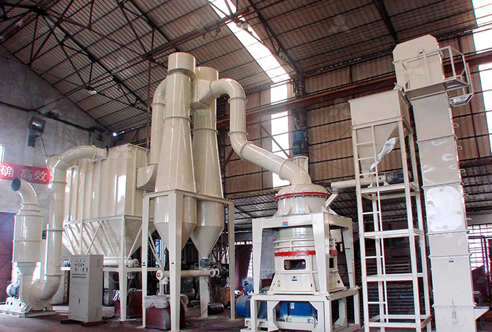
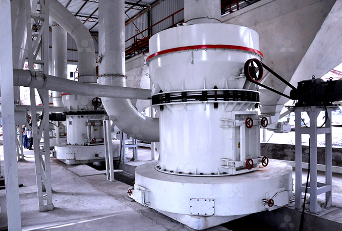
Raymond Mill
Input size:20-30mm
Capacity: 0.8-9.5t/h
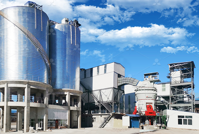
Sand powder vertical mill
Input size:30-55mm
Capacity: 30-900t/h
LUM series superfine vertical roller grinding mill
Input size:10-20mm
Capacity: 5-18t/h
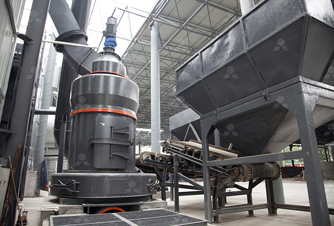
MW Micro Powder Mill
Input size:≤20mm
Capacity: 0.5-12t/h
LM Vertical Slag Mill
Input size:38-65mm
Capacity: 7-100t/h
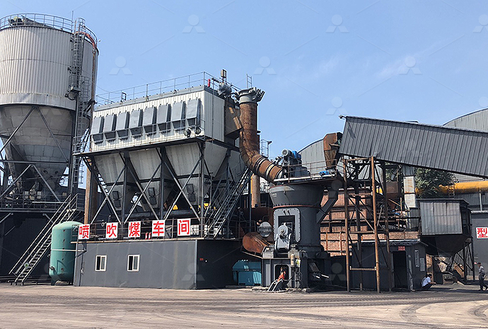
LM Vertical Coal Mill
Input size:≤50mm
Capacity: 5-100t/h
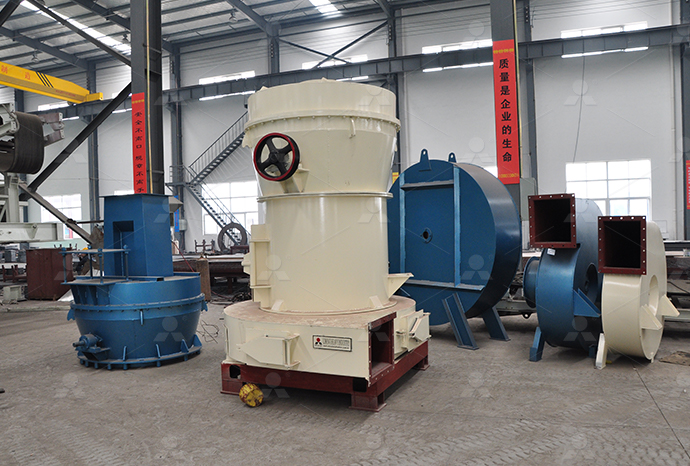
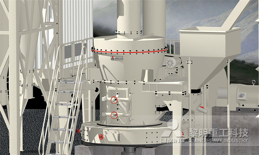
TGM Trapezium Mill
Input size:25-40mm
Capacity: 3-36t/h
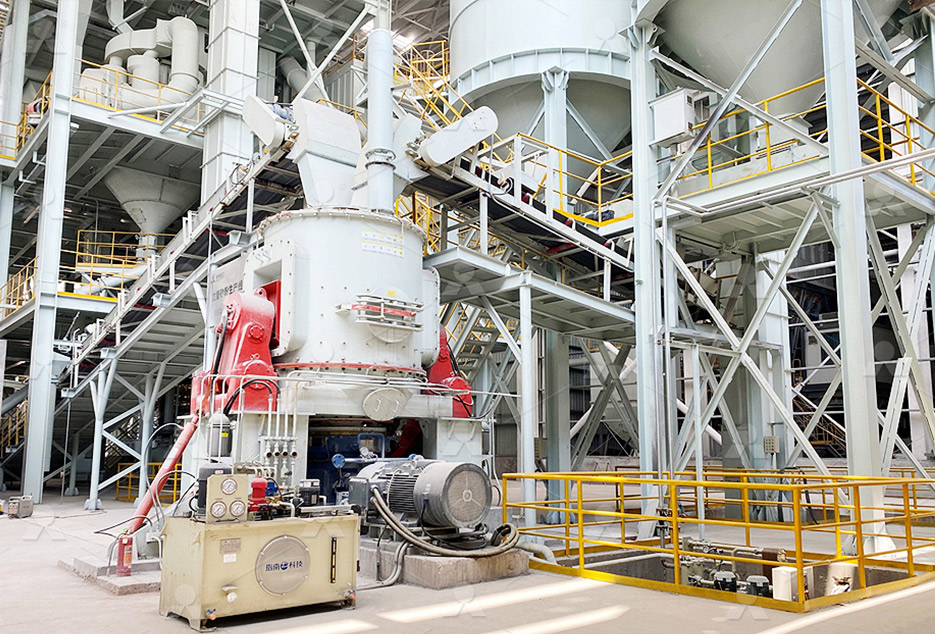
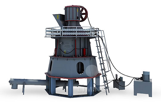
MB5X Pendulum Roller Grinding Mill
Input size:25-55mm
Capacity: 4-100t/h
Straight-Through Centrifugal Mill
Input size:30-40mm
Capacity: 15-45t/h
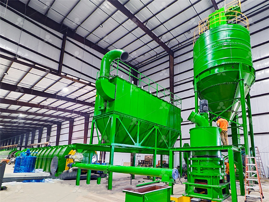
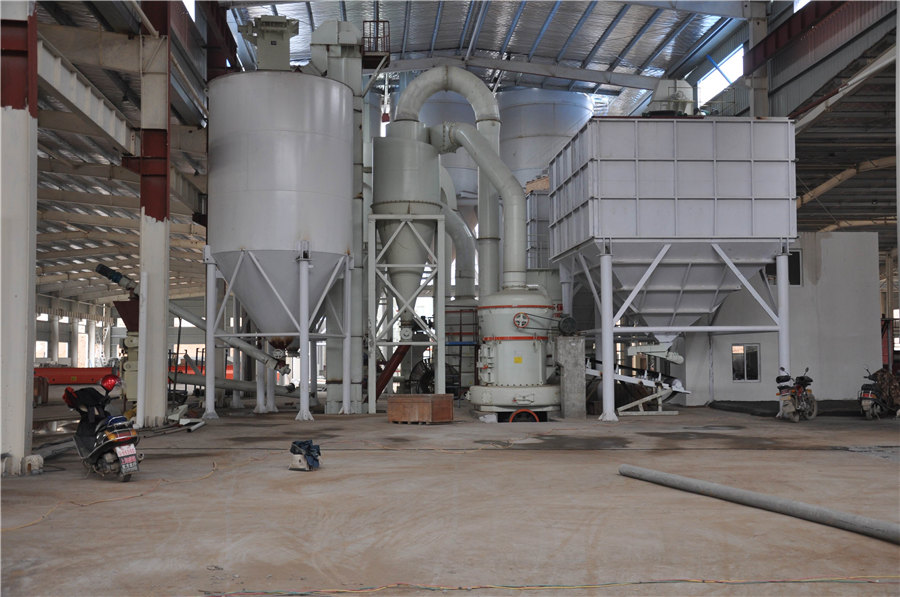
Desulfurization powder process diagram
.jpg)
Flowchart of desulfurization process Download
Leaching (chemical dissolution) is one of the best methods for desulfurising coal, reducing s analyses of the coal samples are presented in Open Journal of Geology made by combining 2 mg ofEste artigo tem como objetivo elaborar uma revisão sistemática da literatura para responder à questão de pesquisa: qual a previsão do comportamento toxicológico de fluidos de perfuração, conhecida Desulfurization process flow diagram Download In this work, 316H austenitic stainlesssteel was prepared by electroslag remelting, and spherical 316H steel powder was produced by a plasmarotating electrode process The powder was sievedSchematic diagram of desulfurization reactions during In most developed countries, wet scrubber (fluegas desulfurization; FGD) technology is a wellestablished process for removing SO2 Also, costs have been reduced significantly from 150 Wet Flue Gas Desulfurization (FGD) ARCOR Epoxy
Flue Gas Desulfurization: Detailed Process Overview
2024年8月13日 Figure 1 below is a simplified process flow diagram for the limestone forced oxidation (LSFO) process, a typical wet FGD system The system is based on absorption of The pipeline injection desulfurization process leverages the flue space between the boiler and the dust collector as a desulfurization reactor, offering a straightforward, spaceefficient, and cost Recent advances in process and materials for dry desulfurization of 2020年4月28日 Onedimensional simulation of synergistic desulfurization and denitrification processes for electrostatic precipitators based on a fluidchemical reaction hybrid modelSimultaneous Desulfurization and Denitrification Using 2022年2月6日 The schematic diagram of HM desulfurization process using powder injection technology is presented in Figure 1 In general, the desulfurization reaction happens mainly in Kinetic Simulation of Hot Metal Pretreatment: Desulfurization
More accurate modeling of flue gas desulfurization in
2022年2月28日 Among them, the semidry flue gas desulfurization technology in powderparticle spouted beds (PPSBs) is considered a reliable and effective desulfurization methodtrating condition Based on the obtained blasting conditions, powder blasting tests were carried out in 300 tscale hot metal desulfurization, and desulfurization flux consumption was decreased by 19% compared with conventional top addition KEY WORDS: hot metal; desulfurization; mechanical stirring; powder blasting 1 IntroductionPowder Blasting in Hot Metal Desulfurization by Mechanical Stirring ProcessDownload scientific diagram Flow diagram of the natural gas desulfurization process from publication: DataBased Optimal Tracking Control for Natural Gas Desulfurization System Flow diagram of the natural gas desulfurization Schematic diagram of desulfurization reactions during the ESR process and spherical 316H steel powder was produced by a plasmarotating electrode process The powder was sieved through screens Schematic diagram of desulfurization reactions during the ESR process
.jpg)
Kinetic Mechanism and Process Optimization of Hot Metal Desulfurization
2022年6月15日 A variablevelocity stirring method is proposed to improve the desulfurization efficiency of highsulfur hot metal for KR desulphurization process2022年7月14日 Carbide slag is a wet powder sample from Zhenyuan ASUS Precious Metals Development Co, Ltd The calcium carbide slag was dried, ground, passed through a 200mesh sieve, and placed in a threenecked flask, and a certain amount of water was added at the set solidtoliquid ratio to carry out a desulfurization experiment at room temperature of 25 ℃Desulphurization mechanism and engineering practice of carbide 4 67 mainly in the transitory reaction zone However, as the removal and stabilization of sulfides 68 after the desulfurization reaction occurs in the permanent contact reaction zone, 69 consideration of this zone, involving top slag, is also very important to simulate the HMP 70 process 71 72 Fig 1–Schematic diagram of hot metal pretreatment with powder injectionKinetic Simulation of Hot Metal Pretreatment: Desulfurization 2017年12月1日 The sulfur concentrations in transport fuels such as gasoline and diesel according to the environmental regulations should be lower than 10 ppm [2]There are several approaches such as adsorptive desulfurization [3], extractive desulfurization [4], biodesulfurization (BDS) [5], hydrodesulfurization (HDS), Oxidative desulfurization (ODS) and Zeolites for adsorptive desulfurization from fuels: A review
Use of limestone for SO2 removal from flue gas in the semidry
Process development of e!ective semidry #ue gas desulfurization by a powderparticle spouted bed Kagaku Kogaku Ronbunshu, 22, 1400}1407 Guo, Q, Kato, K (1998) The e!ect of operating conditions on SO 2 removal in semidry desulfurization by a powderparticle spouted bed Kagaku Kogaku Ronbunshu, 24, 279}284 IEA Coal Research (1997)2017年3月22日 Wire feeder: This process is comparable with powder injection The difference is that the reagents are contained in a hollow wire that is shot into the steel at a speed of 1–4 m s −1 (allowing the wire to penetrate the bath 15–2 m before the coating is completely melted and the reagents are freed)Sulphur removal in ironmaking and oxygen steelmaking2000年7月31日 In the dry sodium desulfurization process, a variety of sodiumcontaining crystalline compounds may be injected directly into the flue gas The main compounds of interest include [14]: • Sodium carbonate (Na 2 CO 3), a refined product of ~98% purity; • Sodium bicarbonate (NaHCO 3), a refined product of ~98% purity; •Dry Flue Gas Desulfurisation Technology ScienceDirect2024年1月10日 Flue gas desulfurization (FGD) is a critical process for reducing sulfur dioxide (SO2) emissions from industrial sources, particularly power plants This research uses calcium silicate absorbent Modeling based on machine learning to investigate flue gas
Desulfurization techniques process and future
2022年7月11日 Due to the most recent environmental requirements, wide desulfurization has become an increasingly important way to obtain ultraclean fuels for transportation of less than 15 ppmw of sulfur, such as diesel, Flue gas desulfurization (FGD) is the removal process of sulfur dioxide (SO2) from flue gases Sulfur dioxide in gases is produced by the combustion of fossil fuels and many industrial processes such as gasoline refining as well as cement, paper, Flue Gas Desulfurization (FGD) Working Thermal Power PlantDownload scientific diagram Schematics of limestoneforced oxidation process (LSFO) from publication: PLEASE SCROLL DOWN FOR ARTICLE Flue Gas Desulfurization: Physicochemical and Schematics of limestoneforced oxidation process (LSFO)Desulfurization is a technology used to separate SO 2 from its emitting sources such as exhaust flue gases of fossilfuel power plants, oil refineries, etc The crucial requirement to decrease sulfur loading in fuels to nearly zero content is imposed by mandatory environmental and health protocols as well as the accurate tolerance needed for their use in fuel applicationsDesulfurization an overview ScienceDirect Topics

Desulphurisation an overview ScienceDirect Topics
Seawater desulfurization process, pure use of natural seawater washing flue gas, A diagram of the heat recovery system is presented in Fig 353 Then the crushed powder is sent to slurry preparation tank for dissolution with water to form limestone slurry2022年10月10日 The experiment proved that the reduced iron powder affects the sulfur in the removed coal When the mass ratio of coal powder to iron powder was 5:2, the best desulfurization effect was obtained at 600 °C for 1 h The desulfurization rate reached 8009%, and more than 7632% organic sulfur was removedDesulfurization mechanism of highsulfur coal by heating 2017年7月11日 As an example of the experimental results, Fig 2 shows the changes in the desulfurization ratio with ① batch addition, ② continuous addition (addition during 0–10 min) and ③ powder blasting (addition during 0–10 min) with low and high gas flow rates With the low gas flow rate (100 NL/min), the increase in the desulfurization rate is small and the powder Powder Blasting in Hot Metal Desulfurization by Mechanical Stirring Processthe slagsteelpowder multiphase reaction in ladle with bottom powder injection is still rarely studied As shown in Fig 2, in the process of bottom powder injection, the multiphase Fig 1 Schematic diagram of new technology of ladle bottom powder injection (Online version in color) Fig 2 Schematic diagram of multiphase flow transport Numerical Simulation of Desulfurization Behavior in Ladle with
A Review of Modeling Hot Metal Desulfurization
1 Introduction Hot metal desulfurization serves as the main unit process for removing sulfur in blastfurnacebased steelmaking Hot metal desulfurization is commonly conducted in a ladle or a torpedo car, 1 using a desulfurization 2020年7月10日 Among all the technologies available, the thermal ZLD process finds the most maturity but requires energy and cost savings (Ma et al, 2016, Onishi et al, 2017)Highsalinity wastewater ZLD in the industry has been encountered (Hu et al, 2019); however, limited data exist concerning FGD wastewater ZLD treatmentTo treat wastewater in the petroleum refinery Process development of flue gas desulphurization wastewater An effective gasphase oxidative desulfurization (ODS) process was proposed The process was studied in a laboratory reactor with a proprietary catalyst at 300400 ºС and ambient pressure with Schematic diagram of integrated desulfurization system and process 2024年5月1日 Schematic diagram of semidry flue gas desulfurization mechanism The desulfurization model is based on the SO 2 mass transfer model proposed by Hill Numerical simulation of semidry flue gas desulfurization process in the powderparticle spouted bed Adv Powder Technology, 31 (1) (2020), pp 323331 View PDF View article View Numerical simulation of particle erosion coupled with flue gas
An evaluation of desulfurization technologies for
The current industrial method for removal of sulfur from fuels is hydrodesulfurization (HDS), which is a high temperature, high pressure catalytic process This makes HDS a very costly option for deep desulfurization Moreover, HDS is not effective for removing heterocyclic sulfur compounds such as dibenzothiophene (DBT) and its derivatives, especially 4,6dimethyldibenzothiophene Download scientific diagram Schematic diagram of the general desulfurization process from publication: A ManyObjective Optimization for an EcoEfficient Flue Gas Desulfurization Process Using Schematic diagram of the general desulfurization processMineralogically identical to natural gypsum, FGD gypsum, or synthetic gypsum, is produced from gas captured within emission control systems at coal fired electric utilities An emission that would compromise air quality, sulfur dioxide (SO2) gas, is the primary contribution coal makes to FGD gypsum Utilities that produce panelgrade synthetic gypsum beneficially reuse FGD sludge FGD Gypsum Production Process2015年10月30日 Phase diagram for CaSO 4 Stability over typical FBC Condition 18) of desulfurization process can be determined by the desulfurization experiment method such as diffusion reaction of the dia(PDF) A Review of Desulfurization Technology using Limestone in
.jpg)
Enhancing the recovery of gypsum in limestonebased wet flue
2017年7月1日 The stateoftheart about the FGD systems includes several studies briefly described Tesárek et al (2007) studied the basic mechanical, hydric and thermal properties of the gypsum obtained from a wet FGD system in order to reuse the gypsum in the construction and building sector Glomba (2010) investigated the role of the parameters influencing the pH 2023年11月20日 In this work, the RHBPI refining process was numerically simulated by establishing a coupled gas–liquidparticle mathematical model The deflection behavior of the gaspowder plume due to powder injection was investigated, and the effects of powder injection location, carrier gas flow rate, powder diameter, and powder injection rate on the circulation Numerical Analysis of Fluid Flow and Powder Transport Springer2021年2月1日 Wastewater treatment proce ss flow diagram 23 Design of process un it waste water by adding a solid powder reagent and energy consumption during the flue gas desulfurization processLimestoneGypsum Wet Flue Gas Desulfurization 2022年2月28日 image: Schematic diagram of desulfurization mechanism in powderparticle spouted bed view more Credit: Feng Wu Sulfur dioxide is the main source of air pollution and easily forms a haze The flue gas desulfurization process in powde
Resource utilization of semidry flue gas desulfurization ash by
2024年4月1日 Semidry desulfurization technology has gained prominence in sintering flue gas desulfurization due to its notable advantages such as minimal equipment corrosion, dry waste products, low water consumption, straightforward processing, and low capital investment, which effectively integrates the drawbacks of wet and dry desulfurization methodsprocess because sulfur in most of steel products is detrimental Ladle bottom powder injection (L–BPI), is a new refining technology that the fine refining powders are injected into liquid steel for desulfurization through bottom slot plugs in ladle,1–5) as shown in Fig 1 This technologyNumerical Simulation of Desulfurization Behavior in Ladle with powder blowing desulfurization during the RH refining process The evolution of the sulfur content was simulated with different initial sulfur contents and desulfurizer qualities Zhu et al[29] established a kinetic model of the powder blowing desulfurization process Effects of the powder blowing rate, the desulfurizerKinetic Model of Desulfurization During RH Refining Process2000年6月1日 A new semidry desulfurization process was tested in this study The process uses the socalled powderparticle spouted bed (PPSB) as the reactor in which coarse medium particles, usually silica sand of several hundred micrometers in size, are fluidized with hot flue gasA slurry of fine SO x sorbent, such as slaked lime or other alkaline powder, is continuously A new semidry desulfurization process using a powderparticle
.jpg)
Modeling on the Desulfurization of the Molten Steel During RH Process
2024年8月7日 The present study integrated the multiphase flow of molten steel, desulfurizer dispersion, and desulfurization kinetics to explore the impact of injection amount, injection speed, and lance position on desulfurizer injection desulfurization This investigation employed a coupled kε model, Volume of Fraction (VOF) model, Discrete Phase Model (DPM), userdefined scalar 2021年4月1日 In pervaporation desulfurization, dense and nonporous polymeric membranes separate the sulfur compounds from other hydrocarbons based on their solubility, affinity, and diffusivity [18] Fig 5 showed a schematic diagram of the pervaporation desulfurization processReview on recent advances in adsorptive desulfurizationDownload scientific diagram Process Flow Diagram of an Anoxic/Anaerobic Biological Treatment System (US EPA, 2015b) from publication: Mathematical Modeling of Biological Selenium Removal from Process Flow Diagram of an Anoxic/Anaerobic Biological2023年8月8日 desulfurization technologies employed in refineries has intensified In today’s refineries, hydrotreatment is the conventional method used for the removal of sulfur and its derivatives via the process commonly referred to as hydrodesulfurization (HDS)5 It is a catalytic process that uses cobalt molybdenum or nickelDesulfurization of Diesel Using Ionic Liquids: Process Design and